7.11 Model for assessing the technical condition, wear and tear, and terms of safe operation of infrastructure
The procedure for carrying out work and calculations using the example of a pipeline
- Formation of an element log and a digital scheme of the pipeline.
According to the passport, structural diagrams of the pipeline, and standards for pipes, connecting parts, and shut-off and control valves, an element log is formed, including:
- item number of the element according to the scheme;
- standard for the pipe / part / valves;
- standard for the pipe / part / valve material;
- spatial coordinates (X, Y, Z) of the start of the element (center of the cross-section);
- spatial coordinates (X, Y, Z) of the end of the element (center of the cross-section).
In addition to those indicated on the diagrams, welded joints between elements, branches at pipeline branching points, and branches at support installation sites are added to the element log.
Pipeline elements (measurement points) are selected where infrasound monitoring devices should be installed during the field survey. For branched pipelines, it is recommended to install devices in the end zones (on shut-off valves) and at branching points (tees with flanges). The choice of device installation sites is also limited to areas (parts) without thermal insulation and the accessibility of areas without restricting operation modes.
Performance of field work on pipeline inspection.
During the field inspection, infrasound monitoring devices (IMD) are installed at the measurement points, and measurements and registration of linear accelerations, as well as angular velocities in three mutually perpendicular directions, are carried out.
Based on the measurement results, amplitude-frequency characteristics of displacements and rotation angles of the pipeline points are constructed.Calculation of the stress-strain state of the pipeline.
3.1. A pipeline section is considered as a spatial flexible frame composed of straight and bent (on elbows) spans of tubular cross-section. Spans consist of pipeline elements (pipes, elbows, transitions, flanges, valves, welded joints, etc.) with parameters (length, diameter, wall thickness, spatial position, material properties) corresponding to the digital scheme (clause 3.1.), each elbow is divided into 4 straight elements. Spans are connected to each other at the locations of equal-passage tees, branches for smaller diameters, and supports. Supports are modeled by bar elements that transmit only axial forces.
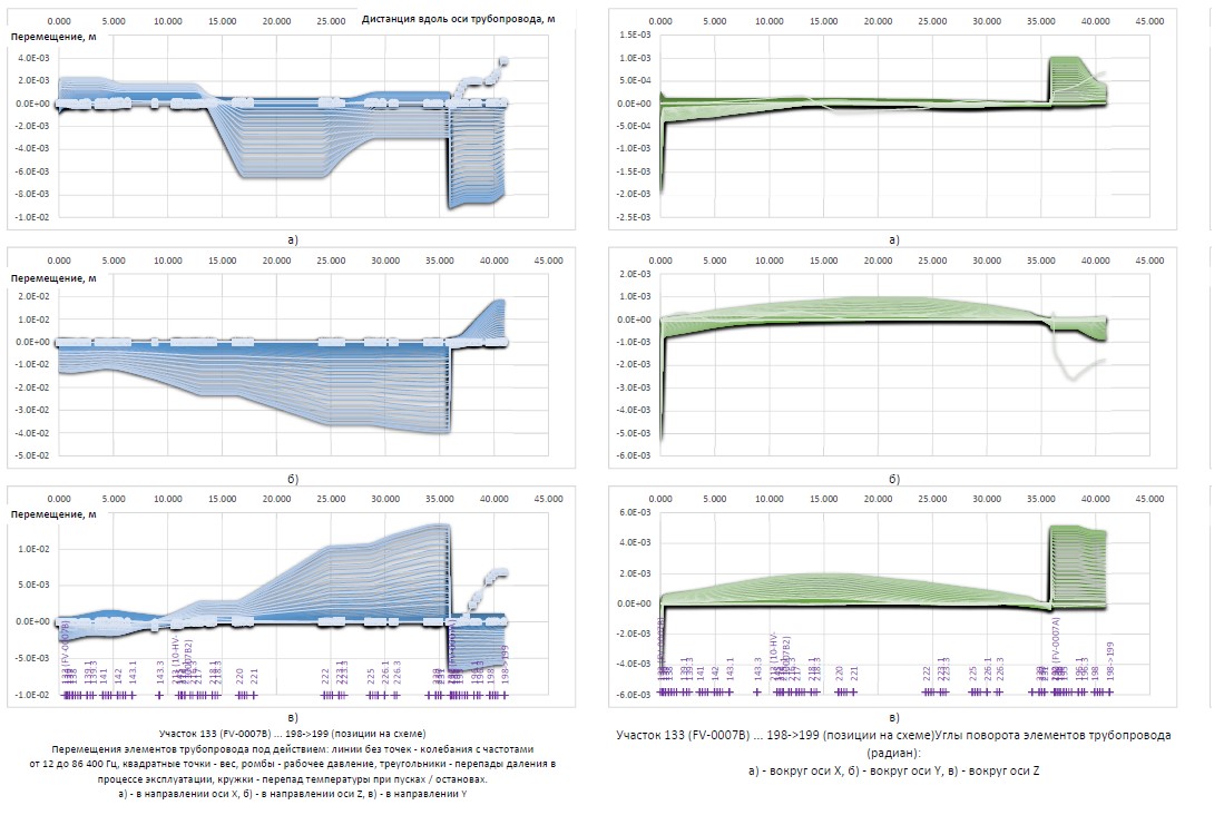
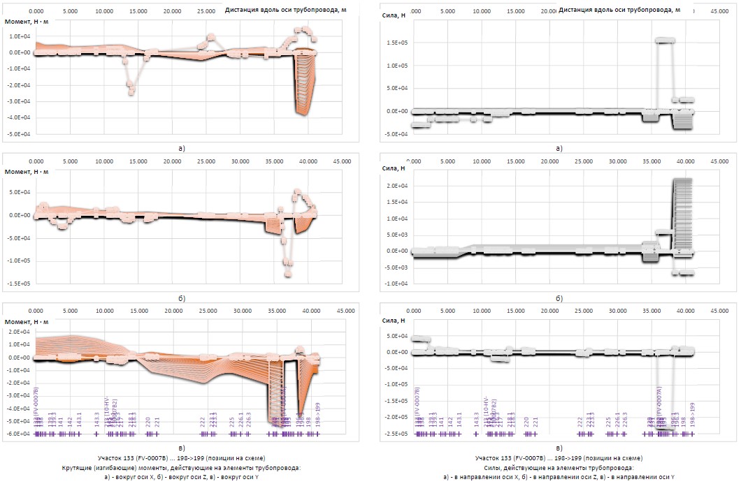
3.2. Calculations of forced dynamic oscillations are carried out with frequencies from 1 Hz to 86400 Hz (65 frequencies). The boundary conditions for the calculations are the amplitude-frequency characteristics obtained from the data of the infrasound monitoring performed. The calculation results (for each pipeline element) are (Figure 1., lines without markers):
- displacements in the direction of the X, Y, Z axes;
- rotation angles around the X, Y, Z axes;
- twisting (bending) around the X, Y, Z axes;
- forces in the direction of the X, Y, Z axes.
Figure 1. Sample. Distributions of displacements, rotation angles, moments, and axial forces
3.3. The calculation of the pipeline deformation under the action of the weight of the pipeline with the pumped product is carried out.
The calculation results (for each pipeline element) are (Figure 1. – lines with squares):
- displacements in the direction of the X, Y, Z axes;
- rotation angles around the X, Y, Z axes;
- twisting (bending) around the X, Y, Z axes;
- forces in the direction of the X, Y, Z axes.
3.4. The calculation of the pipeline deformation caused by the temperature difference during starts / stops and temperature changes during operation is carried out. Linear thermal elongations of individual spans are compensated by the resulting (due to the fastening of the structure and the connection of linear spans) “own” displacements, rotations, moments, and forces. The calculation results (for each pipeline element) are (Figure 1., lines with circles) “own”:
- displacements in the direction of the X, Y, Z axes;
- rotation angles around the X, Y, Z axes;
- twisting (bending) around the X, Y, Z axes;
- forces in the direction of the X, Y, Z axes.
3.5. The calculation of the pipeline deformation caused by the working pressure drop during starts / stops and pressure changes during operation is carried out. Linear elongations of individual spans are compensated by the resulting (due to the fastening of the structure and the connection of linear spans) “own” displacements, rotations, moments, and forces. The calculation results (for each pipeline element) are (Figure 1., lines with diamonds and triangles) “own”:
- displacements in the direction of the X, Y, Z axes;
- rotation angles around the X, Y, Z axes;
- twisting (bending) around the X, Y, Z axes;
- forces in the direction of the X, Y, Z axes.
3.6. For each element, hoop and longitudinal stresses caused by operating pressure and pressure changes during operation are calculated.
3.7. For each element, hoop, longitudinal, and shear stresses caused by torque (bending) moments and forces calculated according to clauses 3.1.-3.6. are calculated.
Conditionally elastic equivalent stresses and corresponding elastoplastic stresses and strains are calculated.
- Strength calculation
4.1. In the strength calculation, a comparison is made of the existing stresses (clause 3.7.) with the permissible stresses according to the project or according to design standards.
4.2. Permissible stresses in design standards are set depending on the purpose (pumped product, temperature, flow rate, pressure), operating conditions of the pipeline (laying method, operating modes, external loads and impacts), characteristics of the metal/material (pipes, connecting parts, valves).
Figure 2. Sample. Existing (dark blue lines) stresses and permissible stresses according to ASME-B31.1 standards (light blue dash-dotted line)
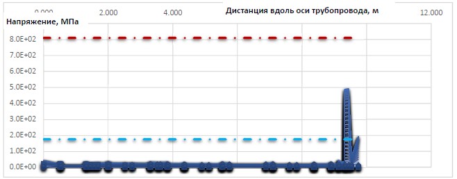
For those pipeline elements in which the acting stresses do not exceed the permissible stresses, further assessment of their state is not required (residual life is not limited by strength).
- Calculation of residual life.
5.1. Based on the stress-strain state of the element (clause 3.7.) and the properties of the pipe metal at a temperature equal to the maximum operating temperature, the probability of failure (occurrence of a crack - destruction of the pipe wall - loss of tightness) is calculated for each type and frequency of loads (clauses 3.2.-3.5.) in one load change cycle from minimum to maximum. The expected failure rate (number of failures per year) is calculated taking into account the number of cycles per year.
5.2. The expected total (from all loads) failure rate from all loads and the failure rate variance, taking into account the stochastic nature of the mechanical characteristics of the metal, operating modes, and a margin for calculation model errors, are calculated (Figure 3.).
Figure 3. Sample. Distribution of failure rate (black line) and 90 % corridor boundaries (green and red lines) along the length of the section
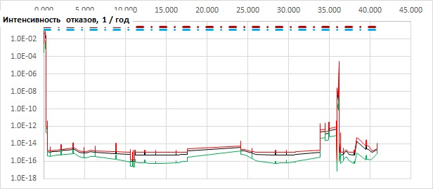
For each element, based on the total failure rate, the residual life is determined (with 95 % probability).
Counting the residual life from the date of the diagnostic inspection, we obtain the safe operation period.
- Main results, conclusions, development of recommendations.
For elements with a residual life of 10 years or less, the causes (types of loads) that lead to a decrease in residual life are determined and a list of compensating measures is developed that ensure the reliable and safe operation of the process pipeline.
Questions & proposals All rights reserved Digital Twin LLC